Geometry and heating method
Plate, tubular, and tube-in-tube refer to exchanger geometry. Direct and indirect UHT describe how heat enters the product. These are related decisions, but they are not interchangeable labels.
Exchanger-selection guide
Plate, tubular, and tube-in-tube describe different heat-exchanger arrangements, but the format name alone does not prove that a UHT system fits a product. Selection should start with product behavior at process conditions, required flow, fouling history, cleaning limits, pressure drop, sterile-line interfaces, and the evidence used for acceptance.
Use the same product and operating basis when comparing proposals. Ask each supplier to show the actual product path, exchanger geometry, calculation assumptions, cleaning boundary, control sequence, and limits of the proposed duty.
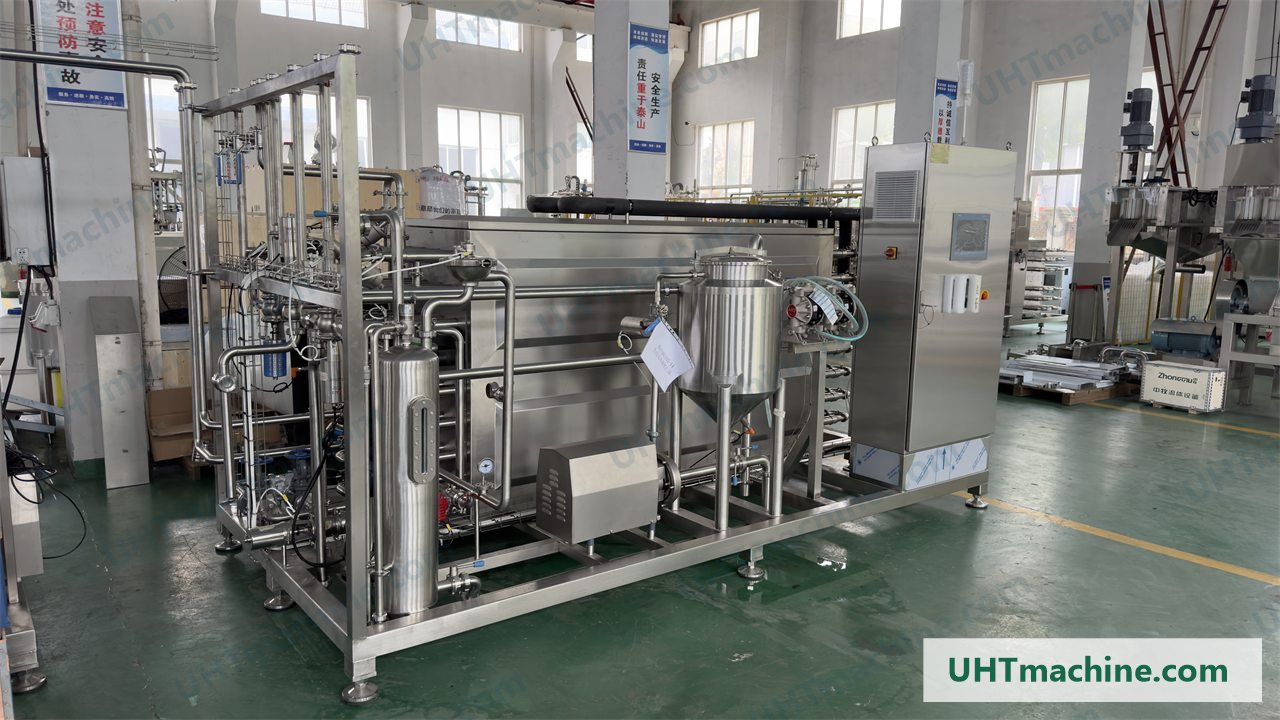
Start with definitions
Plate, tubular, and tube-in-tube refer to exchanger geometry. Direct and indirect UHT describe how heat enters the product. These are related decisions, but they are not interchangeable labels.
Before comparing formats, request a process-flow diagram and exchanger cross-section. Confirm regeneration, final heating, holding, cooling, diversion, and whether any direct-heating module is elsewhere in the line.
Supplier terminology can vary, especially around tubular and tube-in-tube designs. Compare the documented product path instead of assuming that the same name means the same passage, pressure drop, cleanability, or operating envelope.
Product basis
Characterize the product at the temperatures and shear conditions expected in the process. Ambient appearance alone is not a sufficient basis for choosing an exchanger.
Document viscosity across temperature, yield behavior, shear sensitivity, and product-side pressure limits. Ask how the proposed path and pump were checked across startup, normal operation, turndown, and shutdown.
State the maximum expected dimensions, distribution, shape, deformability, and concentration. Review every restriction, valve, bend, pump, holding section, and downstream connection rather than only the main exchanger passage.
Describe solids, fat, protein, starch, stabilizers, acidity, dissolved gas, heat sensitivity, separation behavior, fouling observations, and finished-product attributes. Use a representative product trial and agreed acceptance method where the fit remains uncertain.
Conditional comparison
Use identical product, flow, operating, cleaning, utility, line-interface, and acceptance assumptions for every proposal. The questions below are a comparison framework, not a universal ranking.
| Decision point | Plate | Tubular | Tube-in-tube |
|---|---|---|---|
| Product information | Confirm that the proposed channel geometry fits the documented viscosity, suspended material, fouling behavior, and cleaning method. | Confirm that the selected tube arrangement fits viscosity, solids, fibers, flow distribution, and the required operating range. | Confirm that the actual passage, restrictions, bends, and transitions fit viscous or particulate product behavior. |
| Drawing evidence | Request the plate-pack paths, channel arrangement, gasket and product-contact boundaries, connections, and opening or inspection method. | Request the tube arrangement, headers, distribution points, connections, holding section, drainage, and cleaning circuit. | Request a cross-section showing the concentric product path, changes in flow area, transitions, connections, holding section, and cleaning circuit. |
| Hydraulic basis | Review the calculation basis for flow distribution, pressure drop, pump duty, turndown, and product shear. | Review velocity, pressure drop, path-to-path flow balance, pump duty, turndown, and product shear. | Review annular flow, restrictions, pressure drop, pump duty, turndown, and product shear. |
| Fouling response | Ask how changes in differential pressure, heat transfer, temperature, and run time are detected and linked to diversion or cleaning. | Ask where fouling is expected, how it affects parallel paths, and how operating trends trigger diversion, inspection, or cleaning. | Ask how fouling within the defined passage affects pressure, heat transfer, product recovery, and the cleaning decision. |
| Cleaning and inspection | Define the CIP circuit, flow basis, chemical and thermal limits, drainage, gasket boundary, opening method, and post-cleaning checks. Visual access alone does not prove cleaning performance. | Define the CIP circuit, cleaning-velocity basis, distribution, bends, drainage, inspection points, and evidence used to release the closed circuit. | Define cleaning flow through every annular section and transition, drainage, recovery, inspection access, and the evidence used to release the circuit. |
| Multi-product duty | For every format, require a documented operating envelope covering each formula, product condition, flow range, product change, and cleaning sequence. | For every format, require a documented operating envelope covering each formula, product condition, flow range, product change, and cleaning sequence. | For every format, require a documented operating envelope covering each formula, product condition, flow range, product change, and cleaning sequence. |
| Line integration | Map filler, aseptic buffer, homogenizer, sterile and utility boundaries, control handshakes, diversion, and restart conditions. | Map filler, aseptic buffer, homogenizer, sterile and utility boundaries, control handshakes, diversion, and restart conditions. | Map filler, aseptic buffer, homogenizer, sterile and utility boundaries, control handshakes, diversion, and restart conditions. |
| Acceptance evidence | Agree the trial, calculation review, FAT, cleaning evidence, records, exclusions, and measurable acceptance criteria. | Agree the trial, calculation review, FAT, cleaning evidence, records, exclusions, and measurable acceptance criteria. | Agree the trial, calculation review, FAT, cleaning evidence, records, exclusions, and measurable acceptance criteria. |
No format is automatically the best choice. A defensible decision connects the real product envelope to documented geometry, calculations, trials, cleaning evidence, line interfaces, and acceptance criteria.
Operating reality
Nominal flow does not show how long a line can remain within its agreed operating limits or how it returns to production after cleaning. Compare fouling behavior, pressure and temperature trends, diversion logic, cleaning boundaries, and release conditions for the actual product schedule.
Review the channel arrangement, gasket and product-contact boundaries, drainage, cleaning circuit, opening method, inspection plan, and product-specific evidence. Access for visual inspection does not by itself prove a repeatable cleaning result.
Review the number and arrangement of product paths, distribution points, bends, connections, drainage, cleaning-flow basis, inspection points, and the method used to detect fouling in a closed circuit.
Use a sectional drawing to trace the product passage and every change in flow area. Connect rheology, particles, pressure drop, cleaning flow, drainage, and product recovery to that documented geometry.
Complete-line fit
Evaluate each format as part of the complete UHT line. Include stable operating range, product changes, startup and shutdown behavior, filler interruptions, aseptic buffering, homogenization position, product recovery, utility limits, control handshakes, diversion, and restart conditions.
Require every proposal to state what is included, what is supplied by others, and who is responsible for each product, sterile, control, utility, and validation interface. A suitable exchanger can still produce an incomplete line if those boundaries are not assigned.
Connect product trials, calculation review, FAT, site testing, cleaning evidence, instrument records, operator procedures, and final acceptance criteria. Record the proposed limits and exclusions so that competing offers remain comparable.
RFQ inputs
Buyer questions
Neither format is universally better. The useful choice depends on the actual product, flow behavior, particles, fouling, pressure drop, cleaning method, production schedule, utilities, sterile interfaces, and acceptance evidence. Compare proposals using the same product and operating basis.
Terminology varies between proposals. Tube-in-tube is a tubular arrangement, but the actual product passage, number of concentric sections, transitions, bends, connections, and heating-media path can differ. Request a sectional drawing instead of selecting from the label alone.
Tubular describes exchanger geometry, while direct and indirect describe how heat enters the product. A line can use tubular sections for indirect heating, regeneration, or cooling and may also include a separate direct-heating module. Confirm the complete process-flow diagram.
It can when the documented operating envelope covers every formula, particle condition, flow rate, pressure, fouling behavior, cleaning cycle, and downstream interface. Test the difficult products and changeover cases rather than assuming that one successful duty covers the full range.
Review product data, the process-flow diagram, exchanger cross-section, hydraulic and thermal calculation basis, pump and valve selection, fouling assumptions, CIP and sterile procedures, control narrative, trial evidence, FAT plan, interface list, exclusions, and acceptance criteria.